Marconi
Jan 1990 to Aug 1991
Sector:
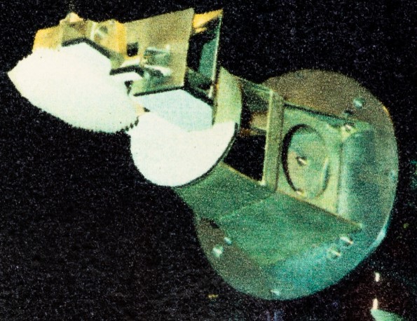
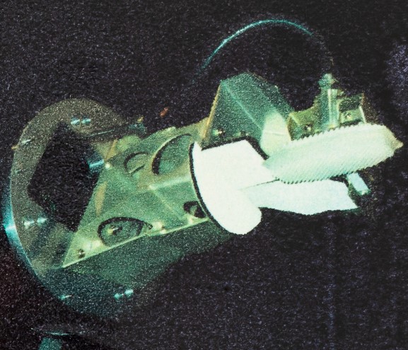
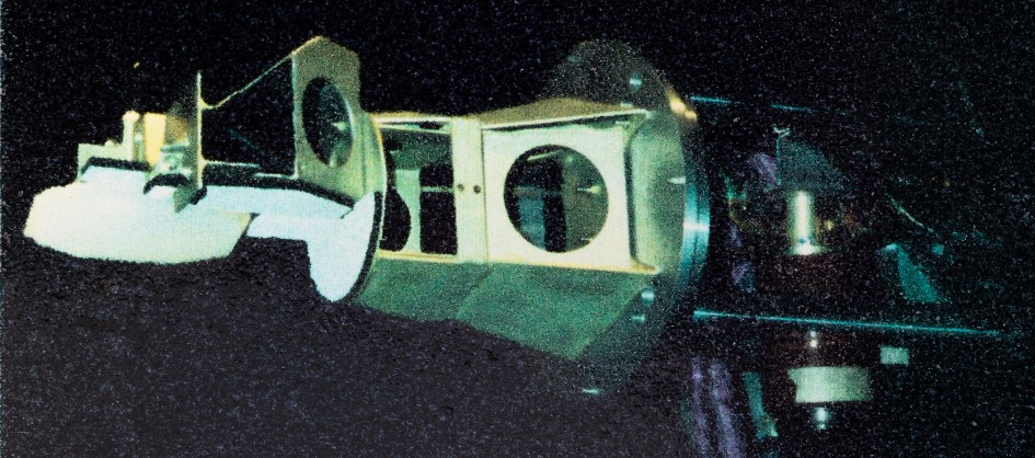
Defence electronics packaging for Aero Radar inside a wingpod.
Overview:
Defence radar equipment layout in a wing pod for combat simulation training purposes.
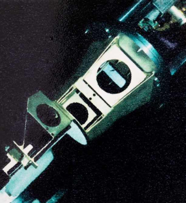
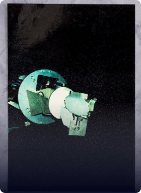
Electro-mechanical packaging of radar components with an adjustable directional ‘Horn’ mechanism in to a wing-pod.
First of a kind ‘clean sheet’ design on 3D CAD from a Design Spec document..
Worked comprised:
Complex problem solving for flexi items in a tiny space to pass vibration sweep and resonance tests.
The design also involved:-
Heat dissipation, Cantilever resonance calcs, Aircraft C of G limits, BS 308 and BS 5750 Draughting standards, Department liaison, and Design reviews.
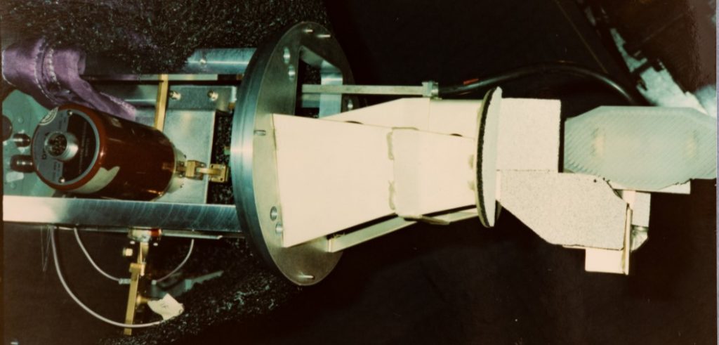
Full details of this role:
A full time ‘permanent’ [sic] role as Mechanical Design Engineer with a large defence radar company, using Computervision CADDS 4X equipment in 3D & 2D environments.
Responsible for Electronics packaging mechanical design, detailing, calculations, & BoM of adjustable radar mechanism for aircraft wing-pod.
A ‘first of a kind / clean sheet’ design from a ‘Requirement spec’ document. Worked to BS 308 & 5750 drawing standards for defence application.
Chronic design compromise problems solved. (Flexible equipment to pass resonance shake tests, aviation environments, small space etc.)
Radar electronics housings designed as part of the work scope, & heat dissipation required in the wing-pod tray.
Manually calculated cantilever resonance equations, & the design fell fully within inertia & C of G limits for aircraft turn rate criteria.
Liaised with many departments, project control, and customer.
Attended project review meetings regularly always achieving design approval.
Role ended with being made redundant due to huge cuts in defence spending after the ‘Cold War’ ended.
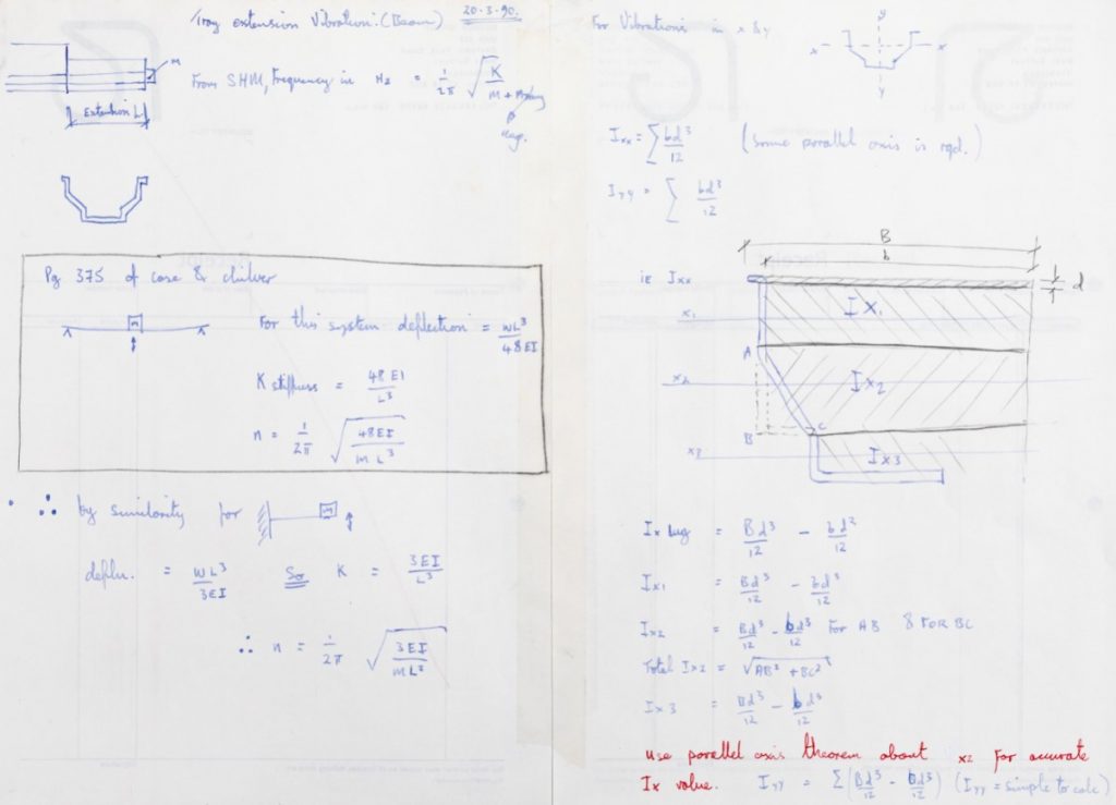
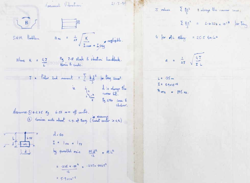
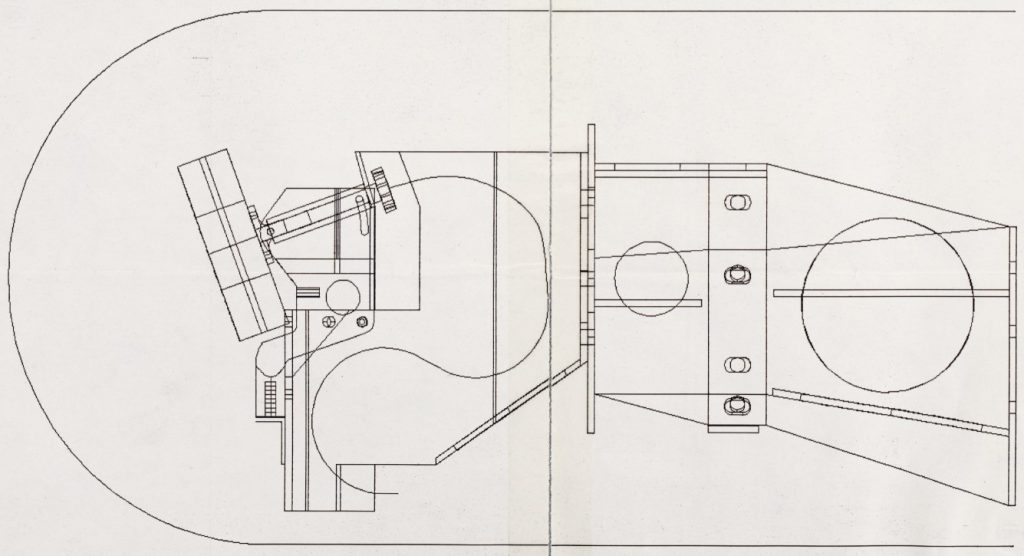
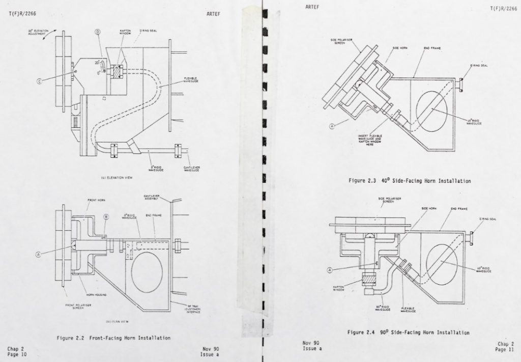
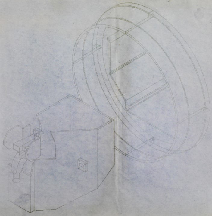
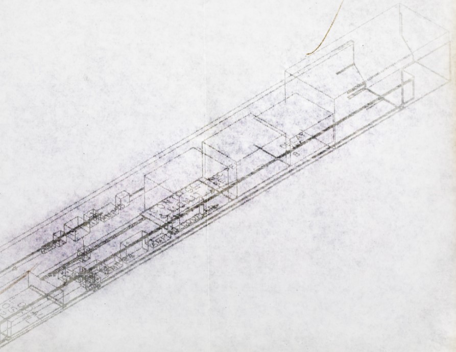
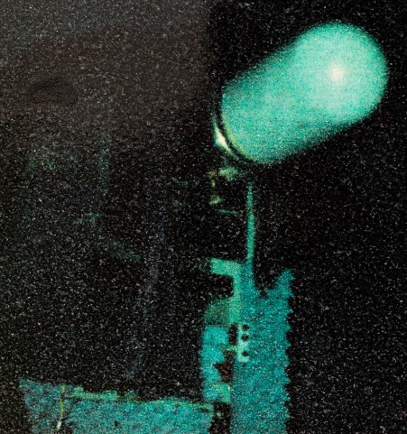
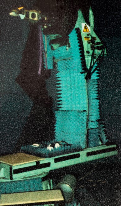
Other Images for this Role (Test chamber images showing wingpod disc and radar horn cantilever frame.)
